A Report on the High School’s Active Science Project 2004.
Reproduction of Herschel’s Metal Mirror Telescope
Chika TAKAMORI,
Yoshimi TOKORO, Tokiko KAMIKUBO, Yuka KANAZAWA, Ayako OHATA,
Shino
HIRABAYASHI, Aoi ISHIDA, Mayuri NISHITANI and Yumi KOMORI
Geography and
Astronomy Club of Ibaraki Prefectural Mito Second High School
Abstract
We had
already built an aerial telescope after three years’ worth of efforts,
and we decided to construct a metal mirror telescope for our next
project, which succeeded the aerial telescope historically. We
selected the 7 feet telescope as a model, with which William Herschel
discovered Uranus in 1781. The metal mirrors were made of an alloy
containing 7 parts copper to 3 parts tin and cast in the same manner
as Herschel’s mirror. The molded metal disks had a great deal of
unevenness, with many pores and bubbles on the surface. We roughly
removed them using a rock-grinder at the school, and then the mirrors
were ground precisely at the Hidaka Optical Laboratory. Finally, we
constructed the telescope with metal mirrors and an octagonal wooden
tube, just like the original instrument.
I. Introduction
|
 |
|
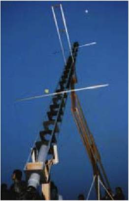
Fig.1 Viewing the moon
with the aerial telescope. |
We, members
of the Geography and Astronomy Club of Mito Second High School, had
spent three years reproducing an aerial telescope. The telescope we
made was 10 meters long, and in spite of its single lens, it had
little chromatic aberration and produced quite a fine view. But
because of its length, we found it very hard to operate and
painstaking with which to observe.
Though it
had been reinforced with wires stretched in a cross direction to
prevent rolling, it was unsteady with even a little wind, making it
difficult to keep the object in the field of view.
As the
efficiency of speculum reflecting telescopes improved, air telescopes
which were difficult to handle gave way to reflecting telescopes. And
after Hevelius’ 150 feet telescope (15cm aperture and 46m focal
length) burnt, they were no longer used.
The man who
rapidly improved the efficiency of speculum reflecting telescopes was
W. Herschel. He constructed many telescopes with mirrors polished by
himself and produced brilliant results. For this reason, we decided to
reproduce a speculum reflecting telescope, which launched a new age in
telescope construction, after aerial telescopes. Our goal for this
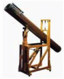
year was to reproduce the 7 feet telescope, with which W. Herschel
discovered Uranus (15.8cm aperture and 2.13m focal length).
II. William Herschel: Short Biography
|
 |
|
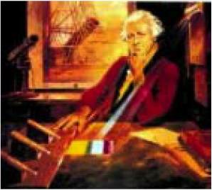
Fig.2 A portrait of
William Herschel |
W. Herschel
was born in Germany. He was a member of the military band belonging to
Hanover Kurfurst in his youth age. After Seven Years War, he went to
England and earned his living as a musician with his younger sister
Caroline. He was naturalized as an English citizen in 1772. He read
the works of Robert Smith of Cambridge, i.e. Harmonics and
Opticks in 4 volumes, and his interest in astronomy quickly
blossomed.
He polished
his first metal mirror in 1773 and made 2,160 mirrors during his life.
He devoted himself not only to making telescopes but also to
astronomical observation with the assistance of Caroline, a
collaboration which resulted in many achievements. Because Herschel
thought magnification was the most important factor in a telescope, he
characterized his instruments by their focal length (instead of their
aperture), which is closely related to magnification.
|
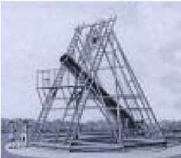
List
of Herschel’s main achievements and the telescope he used.
* The
discovery of Uranus: 7 feet telescope.
* The
observation of spatial motion of solar system: Small 20 feet
telescope.
* The
discovery of planetary nebulae: Small 20 feet telescope.
* The
cataloguing of binary stars: Large 20 feet telescope.
* The
cataloguing of nebulae and clusters: Large 20 feet telescope.
* The
count of stars and advocating convex lens shaped Galaxy theory:
Large 20 feet telescope.
*
Discovery of satellites of Saturn and Uranus: Large 20 feet
telescope.
|
|
 |
 |
|
Fig. 3 Herschel’s
large 20 feet telescope |
Fig. 4 The 7 feet
telescope |
III. Production of the Metal Mirrors
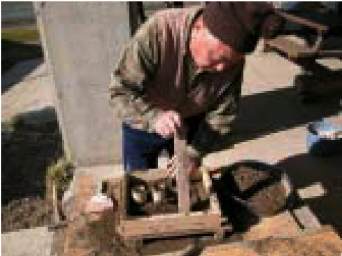
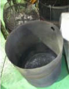
(1) Casting
We
cast our metal mirrors at the Tega-No-Oka Boys’ Nature House on
January 31st of 2004. It was carried out under the guidance of Mr.
Haruo FUKUMURA who lives in Kashiwa, Chiba Prefecture, and who is a
member of the Herschel Society of Japan. The situation at that time
was as follows.
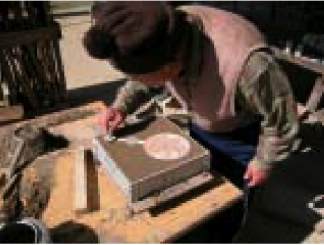
(i) Making the
Sand Mold
|
 |
 |
 |
|
Fig.5 The patterns for the main and
secondary mirrors made previously at the school. |
Fig.6 A board was set under an aluminum
framework to support the patterns for the main mirror and the
gate. |
Fig.7 Ramming the damp sand. |
|
 |
 |
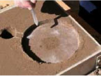 |
|
Fig.8 After ramming the sand, the mold
was inverted. |
Fig.9 The patterns were removed. |
Fig.10 The finished sand mold (which
still needed to be dryed). |
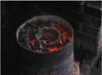
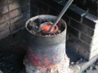
(ii) Pouring
the Melted Metal
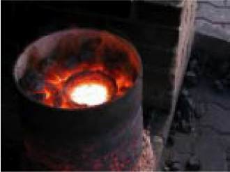
We
ventilated a coke furnace with a blower and heated it to high
temperature. We then poured the molten mirror metal into the sand
mold. The material we used was metal which had been mixed in a ratio
of 7 parts copper to 3 parts tin and melted and cooled previously.
|
 |
 |
 |
|
Fig.11 The melting operation |
Fig.12 Removing impurities |
Fig.13 Completely melted metal (Here
were added some rice straws.) |
|
 |
 |
 |
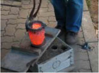
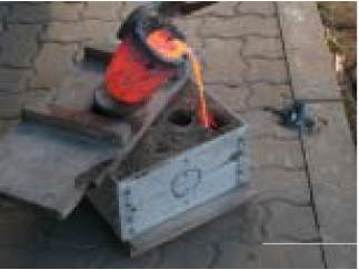
|
Fig.14 A flat board was set up in order
to prevent damage to the sand mold and the crucible was set upon
it. |
Fig.15 Pouring metal into the sand mold. |
Fig.16 Pouring. |
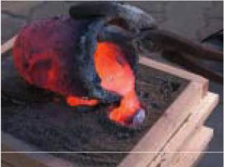
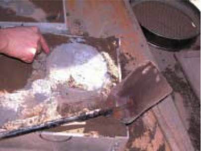
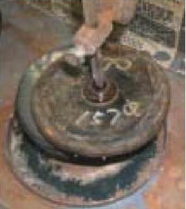
(iii) Removing
the Mirror Disks from the Mold
After
filling the sand mold, we left it to cool for approximately 4 hours.
Then we broke the sand mold apart and removed the mirror disks.
|
 |
|
Fig.17 Removing the mirror disks. |
Though the
alloy was made by mixing relatively soft copper and tin, it became
very hard. Indeed, it was so hard that the grinder used for deburring
was chipped. Perhaps contributing to this, the alloy was not a simple
mixture of 7 parts copper to 3 parts tin. Our first mirror metal was
double cast (or re-melted), being one which had been previously cast
and to which had been added approximately 500g tin (*). This procedure
was said to improve the reflectance of the speculum.
(*translator
note: Because the total weight of alloy is not described, the total
ratio of copper and tin is not clear.)
Finally,
various techniques were used to reduce pores and bubbles. Mr. Fukumura
said “This is a kind of charm…” when he threw cinders of rice straws
into melting pot.
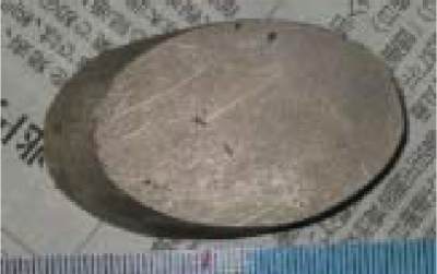
|
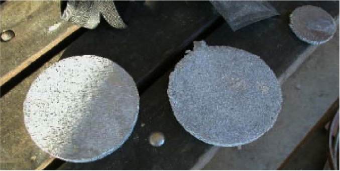 |
|
Fig.18 The two main
mirror disks which we cast at this time. (Only one was made of
double-cast metal.) |
|
 |
|
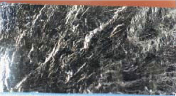
Fig.19 Detail of the surface of the disk |
Fig.19 shows
detail of the surface of the disk. Since it was cast in a sand mold,
it naturally had an uneven surface. At this stage, we were seriously
worried about whether or not it would become a smooth mirror. There
were many burrs around the edge of the disk, so we deburred and
beveled it with a grinder in order to prevent the disk from chipping.
(2) Removing of Pits and Unevenness on
the Surface
After
casting the disks, we tried to remove the small unevenness and bubbles
on the surface as much as possible with a rock grinder, a common
grinder and sandpapers.
|
 |
|
Fig.20 Example of grinding |
When we
ground the disks with a rock grinder and #120 carborundum, the small
unevenness rapidly disappeared, but the deep pits were hard to remove.
Though we often ground over 2mm in depth, some pits still remained and
we had to compromise at a passable condition.
Next, we
ground the disks with finer #300 carborundum. In case some rough
carborundum remained in the pits, we cleaned the surface with a brush
proceeding. When we finished with #300 grit, the work to be done at
the school was completed.
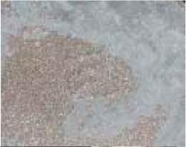
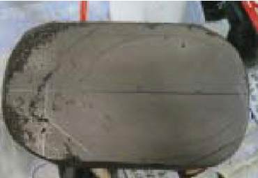
As for the
secondary mirror, we tried to shape it with a grinder. But when we
were grinding the center of the disk, it broke completely. The cause
was the deep pore shown in Fig. 21 (the black patch in the center),
which penetrated the disk. It was not until the disk was broken that
we found out its metal crystalline structure extended vertically
through the disk.
|
 |
 |
|
Fig.21 The broken secondary mirror disk |
Fig.22 A section of the broken mirror |
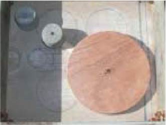
(3) Precise Grinding (1)
After rough
grinding at school, we ground the disks more precisely at the Hidaka
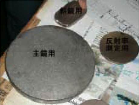
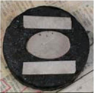
Optical Laboratory. Fig.23 shows the disks to be ground.
|
 |
 |
|
Fig.23 Above: The disk for the secondary
mirror, Below left: The disk for the main mirror, Below right:
The disk for reflectance measurement. |
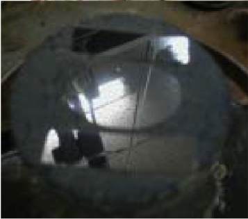
Fig.24 Grinding with an iron plate |
|
 |
|
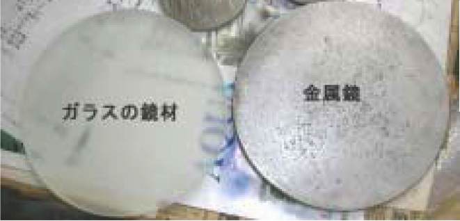
Fig.25 Left: The glass disk, Right: The
metal disk |
We
started by grinding the main mirror, which was double cast and
contained a little more tin. First, we gave it a 4200mm radius of
curvature (R=4200mm) with an iron plate of the same curvature and #240
carborundum. We reduced the pits and pores as much as possible in this
process.
While Mr.
Yojiro Ogane’s “A Report on the Reproduction of a Speculum” (which
appeared on the web site of the Herschel Society of Japan) said that
speculum mirror disks were very hard to grind, our disks were
relatively easy to grind. As the ratio of tin increases, the metal
seemed to soften significantly. Nevertheless, the pits and pores on
the surface were not easily removed, and it took a full day to finish
this operation. After grinding away about 2mm in thickness, the pits
and pores disappeared and the mirror became visually smooth.
|
 |
 |
|
Fig.26 After grinding, the pits had been
reduced. |
Fig.27 Detail of the surface. There were
many small pits. |
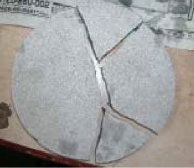
Next, we
tried to grind the disk with #400 carborundum, but the edge of the
disk became so sharp that it was in danger of being chipped. So we
attempted to bevel it and washed it with tap water. But hardly had the
water splashed on it when the mirror broke into pieces. Mr. Hidaka
told us that it was probably because we had scraped over 2mm from only
one side of the disk and strain within the disk resulted in it
breaking. He advised us that we should employ heat treatment
(annealing) to reduce the strain.
|
 |
 |
|
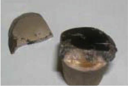
Fig.28 The mirror disk broken in four
pieces . |
Fig.29 A section of the mirror (see
Fig.22. The appearance is quite different). |
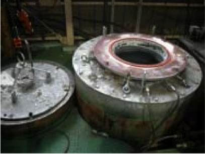
(4) Heat Treatment of the Mirror Disks
We wanted
the advice of Mr. Ogane, a member of the Herschel Society of Japan, on
the matter of annealing. Though the company Mr. Ogane had founded was
no longer in business, we were able to get some advice from Mr.
Osakaki, the former company president. According to him, the key was
to heat a disk up to 590 ± 10°C in an electric furnace, maintain that
temperature for two hours and then allow it to cool gradually in the
furnace.
We searched
on the internet for a metalworking firm around Mito city and found
Metal Engineering and Research Industries, Inc. We phoned them and
inquired whether they could undertake the heat treatment which we
needed. Fortunately, they readily agreed to our request without
charging a fee. We sent three other disks (disks for another main
mirror, secondary mirror and for reflectance measurement) to the
company right away. After a while, we were informed that the heat
treatment was complete, went to get the disks and took that occasion
to tour the factory.
|
 |
 |
|
Fig.30 The container in which our disks
were put. |
Fig.31 The electric furnace with which
the disks were heat treated.
(They said it was a rather old-fashioned furnace).
|
(5) Precise Grinding (2)
We brought the
heat treated mirror disks to the Hidaka Optical Laboratory to have the
fine grinding done again.
(i) Grinding the Main Mirror
This time the
disk for the main mirror was not a double-cast one, but one instead
made from a copper-tin alloy, the ratio of which was precisely 7 parts
copper wire to 3 parts tin stick. Shown in Fig.32, there were many
pits and pores on the surface and periphery. In addition, it was very
solid and hard to grind as written in Mr. Ogane’s report.
|
 |
|
Fig.32 Before grinding. Many pits
remained. |
We placed the
disk on an iron plate 160mm in diameter and fixed with tape on the
periphery. Next, we ground it by an iron plate (R=4200mm) and #240
carborundum while exerting some pressure on it, and removed the pits
and pores as much as possible (see Fig.33). We continued this process
for half a day and removed a considerable number of pits and pores
(see Fig.34).
At this
stage, we decided it was impossible to remove all the pits and pores,
so we continued to grind with #400, #600, #1000 carborundum and
proceeded to final polishing. Whenever we used finer carborundum
grades, we had to wash the disk with a brush in order to remove the
coarse carborundum from the pits completely.
For
polishing, an asphalt plate (pitch lap) was used instead of an iron
plate, and into this was cut a pattern of fine squares, as in a mesh
(see Fig.35). We set the disk under the pitch lap and polished it on a
polishing machine. Cerium oxide was used as an abrasive.
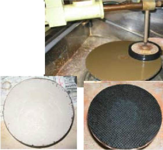 |
Fig.33
(Above)
The
process of fine grinding.
Fig.34
(Below left)
The
main mirror after fine grinding.
Fig.35 (Below
right)
The
Pitch tool.
|
When polishing
a glass mirror, the polishing slurry would be white, but in polishing
a metal mirror a black slurry was produced. If it had been a glass
mirror, we could have finished polishing in four hours or so, but the
metal mirror did not clear up even after eight hours of grinding. Even
if the central part of the disk became polished, the peripheral part
was as clouded as ever. We solved this problem by using an abrasive
used for silicon crystal grinding. But it still took us more than
sixteen hours in total to complete this process. Moreover, we had to
attend to the machine throughout the operation, because we needed to
feed the abrasive into the machine approximately every five minutes.
|
 |
|
Fig.36 Extended polishing was needed.
|
(ii) Grinding
and Polishing the Secondary Mirror
We ground
the secondary mirror into an elliptic form with a grinder. The
elliptic mirror was difficult to polish with a grinder, so we made a
fixing tool from the broken disks. Before polishing, we fixed the disk
firmly with the tools and pitch (see Fig.39).
 |
 |
 |
|
Fig.37 Marking with a pencil. |
Fig.38 The mirror was formed with
grinder. |
Fig.39 The secondary mirror was fixed
with tools and pitch. |
 |
|
Fig.40 The completed main mirror. (It had
a nice polish.) |
At first,
we polished the disk only with cerium oxide, but it did not become
clear. Instead, it polished badly. So we used abrasive for silicon
crystal grinding together with the cerium oxide.
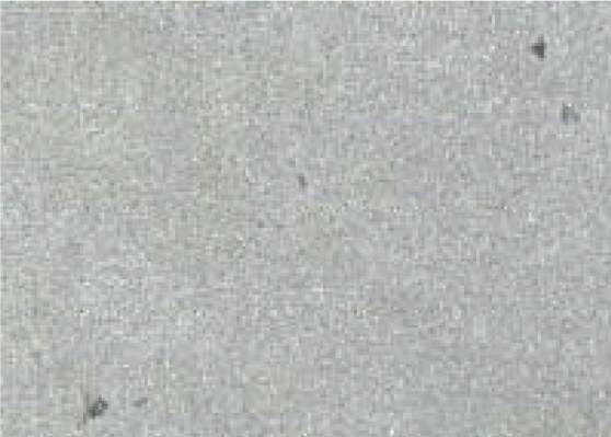
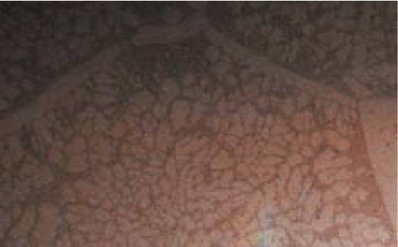
(iii) Close-up
of the polished surface
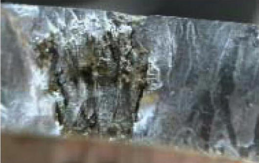
Fig.41 shows
the polished surface of the mirror, which was magnified with a
metallurgical microscope. It is very interesting that the various
crystalline structures are observable. There seems to be a difference
in the hardness between the whitish part and the remaining part of the
surface. This seems to make the grinding operation particularly
difficult. In particular, we had great difficulty in putting a plane
surface on the secondary mirror.
|
 |
|
Fig.41 A close-up of the polished surface
of the mirror,
taken through a metallurgical microscope. |
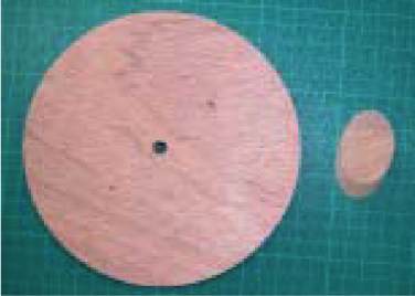
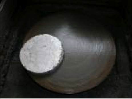
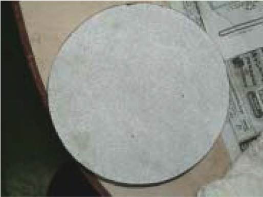
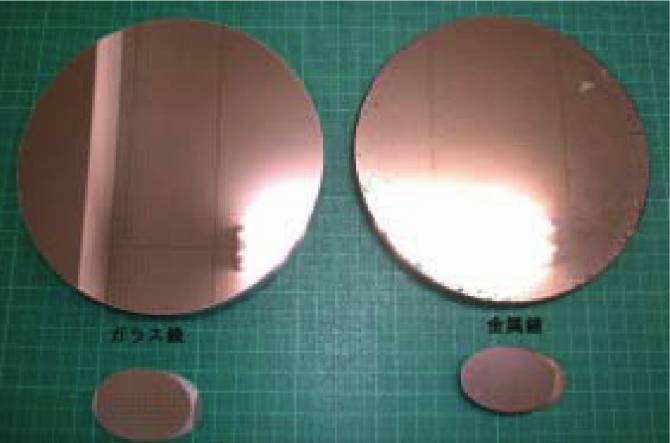
(6) Comparison with a Glass Mirror
In order to
compare the speculum mirror with a metal mirror, we made a glass
mirror of the same aperture and focal length. Though the main mirror
of the Newtonian-type reflector must be a paraboloid, we made our
mirror spherical, because the focal length was sufficiently long and
the difference between the spherical and the paraboloid surface was
under 70nm.
The
light reflected by the metal mirror seemed to be yellowish and the
reflectance was obviously poor. The texture of the surface was
relatively rough too. The pits and pores on the periphery may have
caused a deterioration of contrast and resolution as well. We are now
planning to measure the reflectance and the reflective spectrum in the
near future. Finally, the metal mirror naturally weighed more than the
glass mirror.
|
 |
|
Fig.42 Left: The Glass mirror, Right: The
metal mirror |
IV. Making a Wooden Tube
According to
the English literature sent by Mr. Fukumura, the material which
Herschel used for the tubes of his telescopes was oak or mahogany. And
the ocular part seemed to have a sliding system. At first, we tried to
reproduce such an octagonal tube, 2m in length and 20cm in bore, by
subcontracting the work. But the cost would have been so expensive
that we gave up on the plan. Although it was entirely different from
Herschel's original telescopes, we made an octagonal tube from lauan
plywood. And because of the difficulty of making a smooth draw tube,
we purchased a Vixen-made ocular part. But since it was intended for
round tube use, an adapter was needed to join it to the octagonal
tube.
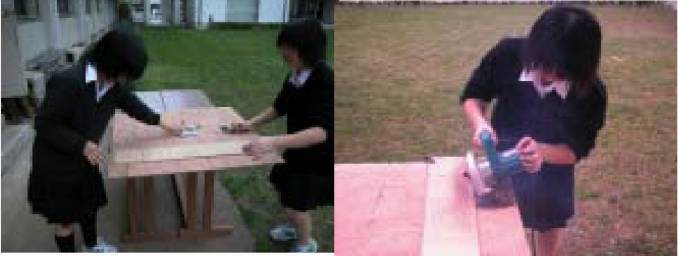
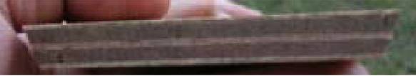
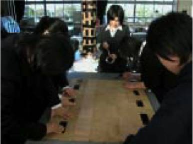
In order to
make an octagonal tube (2m in length and 200mm in bore) from a board
of 11.5mm in thickness, we had to cut it accurately into the same size
parts. The crosscut size would be 93mm on the lower side and 83mm on
the upper side, so the side slope was inclined at an angle of 67.5°.
The only material on hand was a lauan plywood board (1800mm×900mm). It
would have saved us some trouble to cut it lengthways, but as a
practical matter, it was difficult to cut a 1.8m long board straight
even with a circular saw. Consequently we decided to cut it sideways
and assemble sixteen parts into an octagonal tube.
 |
 |
|
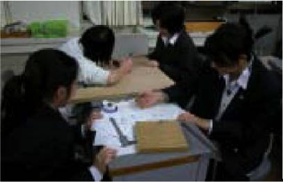
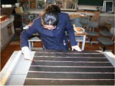
Fig.43 An exact drawing was needed. |
Fig.44 and 45 Fastening a board
with a C clamp as a substitute for a ruler. |
|
 |
 |
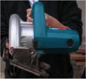
|
Fig.46 The blade was set at an angle
67.5°. |
Fig.47 A crosscut of the board. |
|
 |
 |
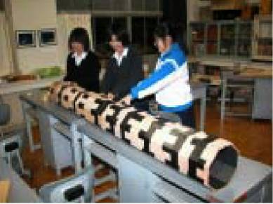 |
Fig.48 The parts were temporarily
fastened
with packaging tape. |
Fig.49 Turning it over and putting
adhesive
into the grooves. |
Fig.50 The tube was fastened tightly
with a packaging tape. |
Fig.51
shows the completed telescope. The octagonal tube was finished with an
oak type paint and mounted on a ready-made altazimuth. The finder was
attached at relatively lower position to observe easily.
|
 |
|
Fig.51 The finished telescope. |
V. Testing the View
Fig.52 shows
the conditions of “first light” which was held on Sunday November 21st
at San-No-Maru Park. On that night, many people enjoyed the view
through the telescope and primarily observed the moon. Because many
pits and pores still remained on the main mirror, we expected the view
would not be particularly good. But when we observed the moon using an
eyepiece of 21mm focal length and power of 100, the view was far
sharper than we had expected, which suggested that a speculum mirror
could produce a fine view as long as it was appropriately ground and
polished.
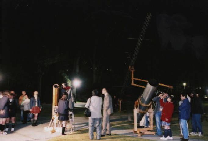 |
|
Fig.52 The evening of “first light”
|
VI. Our Future Projects
1) To observe
and take photos of Uranus.
2) To compare
the views through our metal mirror and a glass mirror (which is now
under construction).
3) To cast a
disk at the school, for which tools and apparatus have been already
prepared.
4) To cast a
disk with less pores and pits.
5) To measure
the reflectance and tarnishing of the mirror.
VII. Acknowledgement
We should like
to thank Mr. Kazumi HIDAKA, the president of Hidaka Optics, Inc. for
his helpful advice and offering an abrasive and a pitch without a fee;
Mr. Haruo FUKUMURA, living in Kashiwa and a member of the Herschel
Society of Japan, for his guidance on mirror casting; Mr. Yojiro OGANE,
for his helpful advice concerning the heat treatment and the grinding
of a metal mirror. Mr. Takahiro SAWAHATA at the Ibaraki Factory of the
Metal Engineering and Research Industries, Inc., for the annealing
operation and for giving us a tour of the factory; Dr. Jun’ichi
WATANABE of the National Observatory, for making time to give a
lecture at the Mito Second High School.
VIII. References
1. Herschel
Society of Japan, their website
2. Shotaro
YOSHIDA, Kyodai Bouenkyou eno Michi (A Road to Giant
Telescopes), Tokabo Press.
3. Henry C.
King, The History of the Telescope.
4. William
Herschel Museum, their website.
5. Smithsonian
National Air and Space Museum, their website.