


Electric Calculator
Application for Filter, Attenuator, CR Time Constant Calculation
If you have any question, click here

Summary
Electric Calculator supports design activity of electronics engineers.
This application provide following 3 functionalities to user.
-
Attenuator design
- T type attenuator
- Pi type attenuator
- CR time delay circuit design
-
Filter design
- Low pass filter (LPF)
- High pass filter (HPF)
- Band pass filter (BPF)
- Notch filter or band elimination filter (BEF)
Usage
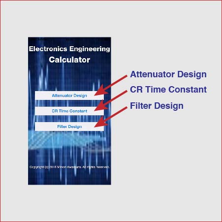
The menu screen shown right figure is desplayed when Electric Calculator is launce.
You can tap one of 3 buttons to perform following fanctinality
- Attenuator Design -- Calculate value of elements of attenuator
- CR Time Constant -- Calculate elements or characteristics of
CR delay circuit - Filter Design -- Calculate value of elements of filter circuit.
アッテネータ設計
When you tap ![]() on menu screen, Pi-Type Attenuator screen is displayed.
on menu screen, Pi-Type Attenuator screen is displayed.
You can design Pi- type attenuator using this screen. When Pi-type Attenuator screen is displayed, icon in bottom shown as ![]() の is blue color.If you tap icon shown as
の is blue color.If you tap icon shown as ![]() , you can move to T-type design screen shown in right side of below. You can change attenuator circuit by tapping bottom side icons. You can back to Menu screen by tapping Menu button located in left side of navigation bar on either pi-type or T-type.
, you can move to T-type design screen shown in right side of below. You can change attenuator circuit by tapping bottom side icons. You can back to Menu screen by tapping Menu button located in left side of navigation bar on either pi-type or T-type.
On the attenuator design screen, after you specify characteristic impedance and attenuation, you can tap "Calculate" button to get value of resiters of selected attenuator. Calculaton result is shown in R1 field and R2 field in red color.
CR Time Constant Calculation
When you tap the ![]() , `CR Time Constant Calculation Screen" is displayed. You can design or analyze specified CR time constant circuit.
, `CR Time Constant Calculation Screen" is displayed. You can design or analyze specified CR time constant circuit.
Graph of upper area shows characteristic of CR ciruit. You can choose charging characterstic or discharging charactersitic by ![]() selecter. The cross cursor is shown in red line on graph area. The "Output" field shows the level of horisontal cursor position and the "Time" fieldd shows the time delay at the vertical cursor position. You can change cursor position by moving bottom side slider of graph area. The values of "Output" and "Time" are following cursor position.
selecter. The cross cursor is shown in red line on graph area. The "Output" field shows the level of horisontal cursor position and the "Time" fieldd shows the time delay at the vertical cursor position. You can change cursor position by moving bottom side slider of graph area. The values of "Output" and "Time" are following cursor position.
By ![]() selector, you can choose the unit of "Output" field as "%" or "Level". When you choose the "Level", it shows the voltage of cursor position. You should input full scale voltage to "Vin" field to use this level unit display mode.
selector, you can choose the unit of "Output" field as "%" or "Level". When you choose the "Level", it shows the voltage of cursor position. You should input full scale voltage to "Vin" field to use this level unit display mode.
Thi function is usuful to design CR time delay to specified voltage level such as TTL input.
You can choose calculation target by ![]() selector. on this selecter, C means capacitor, R means resister, T means time delay, L means output level. The field of item you choose as calculation target change to gray background and red text oolor and you can not input any number to target item field.
selector. on this selecter, C means capacitor, R means resister, T means time delay, L means output level. The field of item you choose as calculation target change to gray background and red text oolor and you can not input any number to target item field.
Whe you tap ![]() button, the selected target item and time constant are calculated and graph cursor is move to specified position.
button, the selected target item and time constant are calculated and graph cursor is move to specified position.
"Tc" field shows "Time Constant" and it is calculated from capacitor value and resister value when calculation is performed.
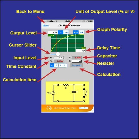
CR Time Constant Calculation Screen
Filter Design
When you tap ![]() on menu screen , "Low Pass Filter Design" screen is displayed.
on menu screen , "Low Pass Filter Design" screen is displayed.
You can design low pass filter with OP-AMP using this screen.There are 4 icons shown as ![]()
![]()
![]()
![]() at the bottom of screen. On "Low Pass Filter Design" screen LPF Icon shows in blue and thers are in gray. you can choose filter circuit by tapping one of these icons. these Icons mean;
at the bottom of screen. On "Low Pass Filter Design" screen LPF Icon shows in blue and thers are in gray. you can choose filter circuit by tapping one of these icons. these Icons mean;
-
 Low Pass Filter
 -
 High Pass Filter
 -
 Band Pass Filter
 -
 Notch Filter (Band Elimination Filter)
A. Low Pass Filter
After you specify cut off frequency and resister value and filter characteristic, you can get 2 of capacitor value by tapping "Calculate" button. You can choose filter characteristic by ![]() selector.
selector.
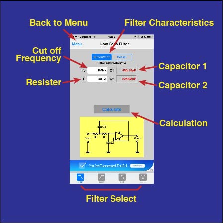
Low Pass Filter Design Screen
B. High Pass Filter
You should specify cut off frequency and capacitor value to design high pass filter. After fill the "fc" and "c" field, you can tap calculate button to get 2 resister values shown in R1 and R2.
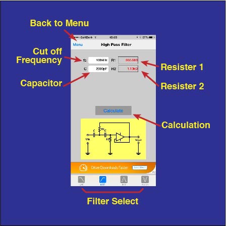
High Pass Filter Design Screen
C. Band Pass Filter
In order to dsign band pass filter, you should specify center frequency, Q, and capacitor value. You can get 3 of resiter value of band pass filter by tapping "Calculate" button with specigfied center frequency and Q and capacitor.
The number of Q should be under 20 because higher Q setting causes unstable circuit.
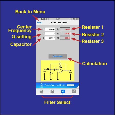
Band Pass Filter Design Screen
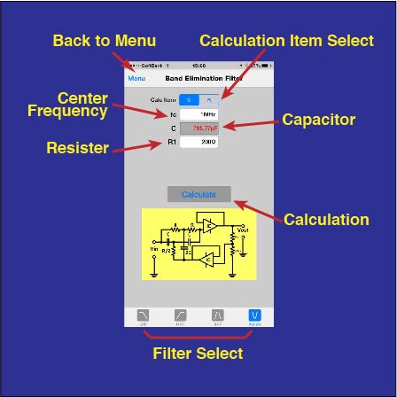
D. Notch Filter ( Band Elimination Filter)
You can choose calculation target from Capacitor and Resister by setting of ![]() selecter. The center frequency and non-selected item capacitor or resister should be specified to perform notch fileter design.
selecter. The center frequency and non-selected item capacitor or resister should be specified to perform notch fileter design.
ノッチフィルタ設計画面
Common Operation Guide
Input Data by Keyboard
when you tap input field which has white background, the appropreate keyboard will be appears.
Keyboard is always Decimal keyboard, so you can input only number or period. it means that you can input only positive number for this application.
The unit selecter and navigation buttons are shown in top of keyboard. When editing is finished, selected unit is added to input number. If you would like to input 1 kΩ as resiter value, type "1" and choose "kΩ" on unit selecter.
Folloing unit selecters are automatically choose
-
 Time
Time -
 resister or impedance
 -
 attenuation (dB)
 -
 retio (%)
 -
 capacitor
 -
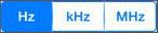 frequency
 -
 level ( Voltage)
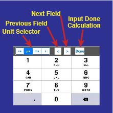
When you tap "previous field" button shown as ![]() , input value of current field is fixed and move to previous ( or upper ) field, then clear that field and appropreate keyboard will be appears. Also when you tap "next field " button shown as
, input value of current field is fixed and move to previous ( or upper ) field, then clear that field and appropreate keyboard will be appears. Also when you tap "next field " button shown as ![]() , input value of current field is fixed and move to next ( or below ) field, the clear that field and appropreate keyboard will appears.
, input value of current field is fixed and move to next ( or below ) field, the clear that field and appropreate keyboard will appears.
When you tap "Done" button shown as ![]() , input value of current field is fixed and keyboard will disappear and execute calculation. This behavior is same as following 2 actions. ( tapping outside of keyboard then tapping "Calculate" button )
, input value of current field is fixed and keyboard will disappear and execute calculation. This behavior is same as following 2 actions. ( tapping outside of keyboard then tapping "Calculate" button )
If you tap the outside of keyboard, the input value of currernt field is fixed and keyboard will disappear.
if the input value is invalid or not suit to field, the alert is displayed when input value is fixed.
When calculation is performed, application checks all input value and the alert is displayed if invalid data is found.

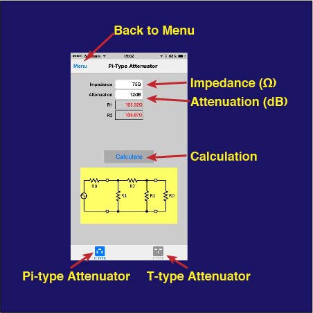
Pi-type Attenuator Design Screen
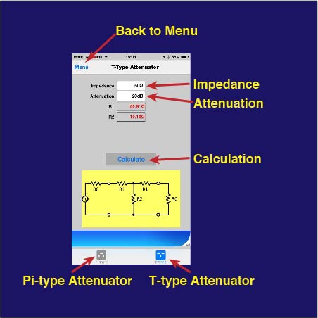
T-type Attenuator Design Screen
Copyright © 2014 AEC Enterprise. All rights reserved.