Fairchild A-10
Thunderbolt II
Download A-10 Drawing(pdf)
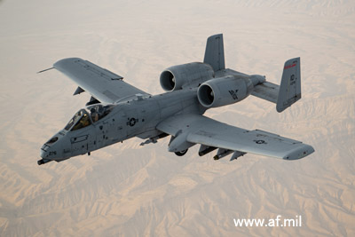
A-10 Thunderbolt II
The A-10 Thunderbolt II was selected from proposals submitted for a
next-generation attack aircraft program launched in 1970, aimed at
addressing the shortage of close air support capabilities
experienced during the Vietnam War. It made its maiden flight in
October 1975, and deployment began in March 1976. Although the
Vietnam War had already ended, large numbers were deployed to Europe
during the Cold War, designed to strike Warsaw Pact armored forces
using a powerful, nose-mounted 30mm cannon capable of penetrating
tank armor. Following the collapse of the Soviet Union and the end
of the Cold War in 1991, some questioned the aircraft's necessity;
however, its distinguished service in the Gulf War, the Bosnian
conflict, and the wars in Afghanistan and Iraq silenced these
doubts, and it remains in active use today.
Its thick, straight wings provide excellent low-speed
maneuverability and allow for a large fuel capacity, while thick
titanium alloy armor around the cockpit and other critical areas
enhances survivability. Large, high-bypass turbofan engines are
mounted on the upper fuselage; this configuration offers low fuel
consumption suitable for long-duration flights, reduces the risk of
foreign object ingestion during ground operations, and helps shield
the exhaust outlets behind the horizontal and twin vertical
stabilizers, making the aircraft less susceptible to infrared
detection. (Source: Ikaros Publications, "World's Famous Aircraft
Series: A-10 Thunderbolt II")
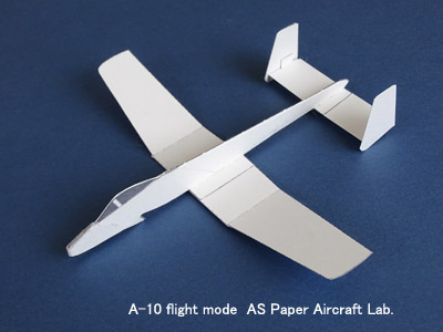
As a paper airplane, its straight-wing design—featuring a higher
aspect ratio compared to typical jet fighters—promises excellent
flight performance.
How to Build the A-10 Thunderbolt II
Print the downloaded blueprints onto heavy paper, such as Kent
paper. Please install Acrobat Reader to view and print the files.
Since the paper is thick, please adjust your printer settings for
cardstock or postcard printing. Gray or silver-gray paper is
recommended to achieve a military aircraft look.
Cut the parts out from the template along the thick lines. Dotted
lines and dash-dot lines indicate mountain folds and valley folds,
respectively; use a ruler to pre-fold these lines before applying
glue. For Main Wing 1, create a slight upward angle (dihedral) of 7°
at approximately the inner one-third mark. Crease the sides of
Horizontal Stabilizer 2 (up and down) and glue together Vertical
Stabilizers 3 and 4; the thin center line should face downward.
Sandwich Cockpit Section 6 between the two pieces of Part 5, then
glue Fuselage Part 7 over this assembly so that the cockpit section
is enclosed inside. Glue the Front Fuselage (Part 8) in place. Next,
attach Nose Cover 9 to cover the nose. Unlike the actual aircraft,
the nose tip will have a flat section; this design feature enhances
safety in the event of a collision and increases the nose's
durability. Attach the main wings and tail assembly to the underside
of the fuselage; the small arrows indicate the direction of the
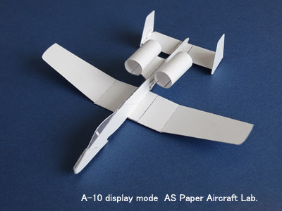
nose. To assemble the engine, wrap the engine nacelle section around
a pen barrel or similar object to curve it, then overlap the inner
glue tabs to form a cylinder. Since the engine is intended for
display, attach it to the fuselage just behind the main wings using
a clip or similar fastener, but remove it before flying. Permanently
fixing the engine increases air resistance and disrupts the center
of gravity, significantly impairing flight performance.
Finishing
Give the main wings a slight upward curve (camber) and check to
ensure there is no uneven twisting between the left and right sides.
If flying the model outdoors, apply a thin coat of lacquer over the
entire aircraft to improve water resistance and strength. A clear
spray lacquer is recommended, as it allows for a thin, even
application. The center of gravity will be in the optimal position
once the model is painted.
**Adjustment and Flight**
When handling the aircraft, hold it by the front-to-middle section
of the fuselage or by the wing roots. The tail assembly and wingtips
lack the structural strength to support the aircraft's full weight;
holding it by these parts can cause deformation or breakage.
View the aircraft from the front and ensure there is no left-right
twisting.
When launching with a rubber-band catapult, it is generally best to
adjust the trim so the nose is held slightly down. Adjust the model
to fly a gentle left-hand turn.
Tilt the aircraft to the right, aim it steeply upward (60–75
degrees), and launch it using the rubber-band catapult.
With proper adjustment, the aircraft will climb while turning and
then transition into a gliding flight at altitude.